Posted on Tuesday, September 23, 2025
When investing in a new roll forming machine, one of the most important steps in commissioning is the setup of compressed air and hydraulic systems. These two systems are the backbone of machine operation, powering everything from light clamping functions to high-force cutting and punching stations.
Improper setup can cause downtime, damage to the machine, and costly delays. Proper setup ensures reliability, efficiency, and safe operation. This guide explains what parts you need, how to install them, and best practices for keeping both systems in peak condition.
Roll forming machines rely on both compressed air and hydraulic power, each serving specific purposes:
Compressed Air:
Used for clamping, guiding, shearing, stackers, and lightweight actuators.
Provides fast and precise movements with low energy cost.
Typically runs at 6–10 bar (90–145 psi).
Hydraulics:
Used for punching, cutting heads, decoilers, and embossing units.
Provides high-force output with smooth, controlled motion.
Typically operates at 120–200 bar (1750–2900 psi).
Both systems must be carefully integrated into the roll former’s control system (usually PLC-driven) to ensure accurate and safe operation.
To set up the air system, you’ll need:
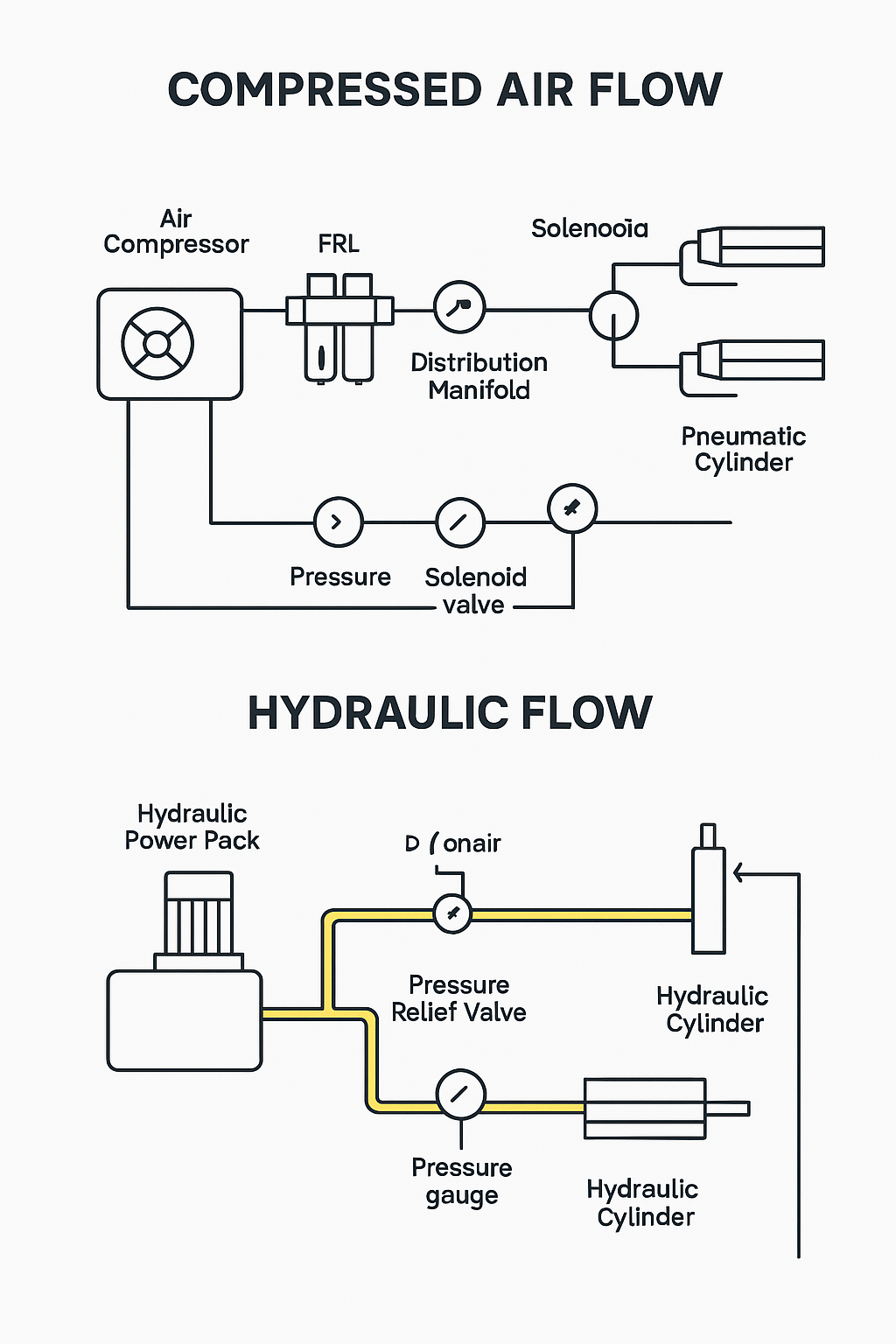
Air Compressor – Supplies compressed air to the system.
Air Dryer/Filter – Removes water, oil, and contaminants.
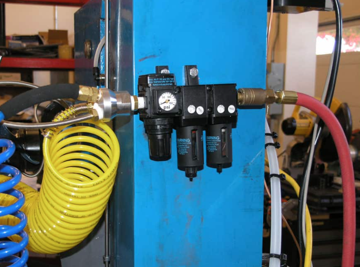
FRL Unit (Filter, Regulator, Lubricator) – Keeps air clean, lubricated, and at the right pressure.
Main Air Supply Line – Usually steel, copper, or reinforced hose.
Distribution Manifold – Splits airflow to multiple machine sections.
Solenoid Valves – Electrically controlled valves that direct air to cylinders.
Air Hoses & Fittings – Connect components and actuators.
Pneumatic Cylinders – Already installed on the machine.
Pressure Gauges – Allow monitoring of supply and working pressure.
Position the Compressor and Dryer
Place in a dry, ventilated location.
Allow space for service access.
Run the Main Air Line
Use steel or copper pipe for fixed lines; reinforced hose for flexible sections.
Ensure proper sizing for air volume.
Install the FRL Unit
Mount close to the machine inlet.
Set regulator to recommended pressure (usually 6–8 bar).
Connect to Manifolds and Valves
Run supply from FRL to manifolds.
Wire solenoid valves into the machine’s PLC.
Check Airflow
Run purge cycle to blow out moisture and debris.
Confirm no leaks in fittings and hoses.
To set up the hydraulic system, you’ll need:
Hydraulic Power Pack (HPP) – Includes tank, pump, and motor.
Hydraulic Oil – Typically ISO 32/46 grade (check manufacturer spec).
Pressure Relief Valve – Protects system from overload.
Directional Control Valves (DCVs) – Direct oil to actuators, PLC-controlled.
High-Pressure Hoses – Fitted with crimped couplings.
Manifolds – Distribute fluid to multiple lines.
Cylinders – Operate cutting heads, punches, decoilers.
Cooling Unit – May be required for continuous-duty operation.
Return Filter & Breather – Keep oil clean and free of air.
Pressure Gauge – For monitoring working pressure.
Position the Hydraulic Power Pack
Place near the machine with easy service access.
Ensure vibration pads are fitted.
Fill the Reservoir
Use the recommended grade of hydraulic oil.
Fill to specified level, leaving headspace for expansion.
Connect Pressure and Return Hoses
Connect hoses from the power pack to machine inlet ports.
Use clamps to secure hoses away from rollers and moving parts.
Run Hoses to Cylinders
Route hoses neatly to each cylinder (shear, punch, decoiler, etc.).
Avoid sharp bends that can restrict flow.
Bleed the System
Run pump at low speed to purge air.
Cycle cylinders slowly until air is expelled.
Set Relief Valve Pressure
Adjust to the manufacturer’s recommended setting (commonly 120–200 bar).
Run Test Cycles
Start at low pressure.
Test all functions before moving to full production.
Compressed air solenoids and hydraulic valves must connect to the machine’s PLC for automation.
Confirm voltage compatibility (typically 24V DC).
Ensure emergency stops cut power to valves.
Tag wiring and hoses for easy troubleshooting.
Here’s a practical checklist your technician can follow:
Compressed Air
Install compressor and dryer in a ventilated space.
Connect main air line to machine inlet.
Fit FRL unit near machine.
Connect manifold and solenoid valves.
Set regulator to 6–8 bar.
Purge line before operation.
Check all hoses and fittings for leaks.
Hydraulics
Position hydraulic power pack near machine.
Fill with correct hydraulic oil.
Connect pressure and return hoses.
Route hoses to cylinders with clamps.
Bleed system to remove trapped air.
Adjust pressure relief valve.
Run low-pressure test cycle.
Inspect for leaks or overheating.
Controls
Connect solenoid wiring to PLC.
Confirm correct voltage supply.
Test emergency stop functionality.
Label hoses, valves, and wiring.
Use rated hoses and fittings—air hoses for air, hydraulic hoses for oil.
Keep air and hydraulic systems color-coded for quick identification.
Avoid routing hoses near rollers, chains, or hot surfaces.
Drain air moisture daily.
Change hydraulic oil and filters every 6–12 months.
Keep critical spares: hoses, seals, solenoid coils, filters.
Train operators in safe startup and shutdown procedures.
Compressed air and hydraulics are the lifeblood of a roll forming machine. Air ensures quick, accurate movements for clamping and shearing, while hydraulics provide the high-force operations for punching, cutting, and decoiling.
By following the correct setup steps—installing compressors, dryers, FRLs, power packs, and hoses properly—you ensure reliable machine performance from day one. A structured checklist approach helps technicians avoid mistakes, improve safety, and reduce downtime.
With proper setup and maintenance, your roll forming machine will run smoothly, consistently, and safely for years to come.
Used Purlin Roll Forming Machines for Sale Worldwide
Posted on Sunday, January 25, 2026
Pre-Owned Roll Forming Machines for Purlin & Structural Steel Profiles
Used Roof Panel Roll Forming Machines for Sale Worldwide
Posted on Sunday, January 25, 2026
Pre-Owned Roll Forming Machines for Roofing Panel Production
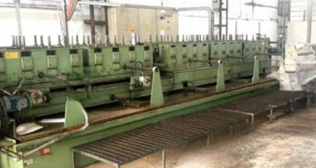
Used Roll Forming Machines for Sale Worldwide
Posted on Tuesday, January 20, 2026
Pre-Owned Roll Forming Machines with Inspection, Verification & Global Support
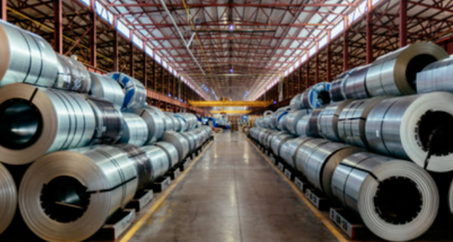
Steel Coil Supply for Roll Forming Machines Worldwide
Posted on Tuesday, January 20, 2026
Reliable Steel Coil Supply for Roll Forming, Fabrication & Manufacturing Applications
Copyright 2026 © Machine Matcher.