Posted on Tuesday, November 11, 2025
Every modern roll forming machine depends on its PLC system — the programmable logic controller that synchronizes mechanical, electrical, and hydraulic operations.
From simple stud & track lines to high-speed decking or purlin systems, the PLC determines how precisely each profile is formed, punched, and cut. When written well, ladder logic becomes the invisible language that turns coils of steel into finished panels, beams, or flashings — efficiently and safely.
At Machine Matcher, we build and supply roll forming machines worldwide, each equipped with industrial-grade PLC systems (Siemens, Allen-Bradley, Delta, or Mitsubishi). This guide explains the structure of roll forming automation, with real ladder logic examples and best practices for engineers and plant managers.
A typical PLC project for roll forming is divided into modules. Each has a defined function and communicates with others through global variables or function blocks.
| Module | Function |
|---|---|
| Main State Machine | Controls operating modes and transitions |
| Safety System | Monitors estops, guards, and light curtains |
| Motion Control | Drives VFDs, servos, and hydraulic axes |
| Feeding & Measuring | Encoders, length counters, and indexing |
| Punching & Shearing | Coordinates valves, blades, and timings |
| Stacker & Conveyor | Handles product discharge and counting |
| Alarm & Diagnostic System | Captures faults and operator messages |
| HMI Interface | Displays recipes, counters, and statistics |
Each module runs cyclically, executing logic in milliseconds to maintain synchronization at production speeds of up to 120 m/min.
A state machine ensures orderly transitions between operational phases:
IDLE → READY → RUN → FAULT → ESTOP
Typical Ladder Logic (simplified)
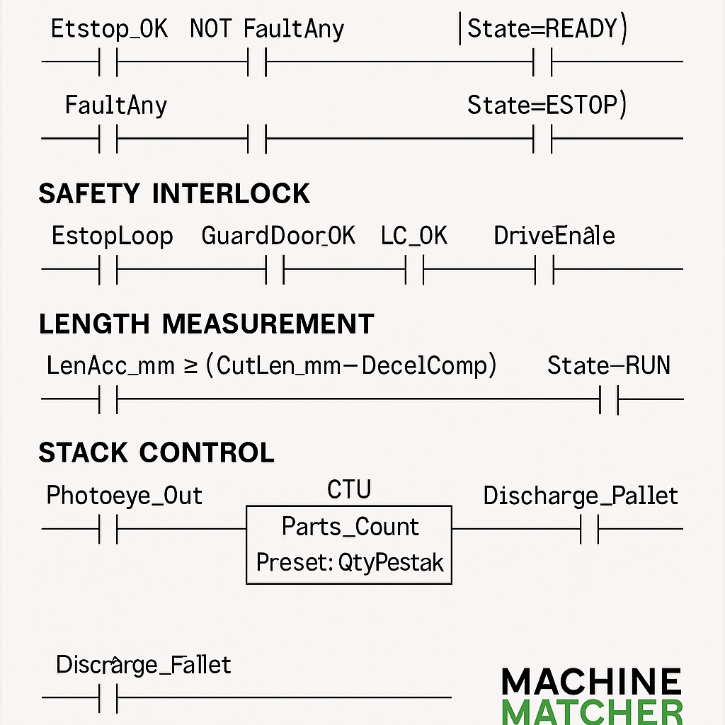
| Estop_OK Safety_OK NOT FaultAny Cmd_Auto |----( State=READY )----|
| State=READY StartPermitted |----( State=RUN )----|
| FaultAny |----( State=FAULT )----|
| NOT Estop_OK |----( State=ESTOP )----|
This approach avoids sudden motion, defines recovery paths, and simplifies HMI indicators.
Safety interlocks protect both operators and equipment.
Key inputs include:
E-Stop loop continuity
Guard door switches
Light curtain signals
Hydraulic pressure switches
Overload relays
When all safety devices are confirmed, a Safety_OK bit enables drives and solenoids. The logic looks like:
| EstopLoop GuardDoor_OK LC_OK HydPress_OK |----( Safety_OK )----|
| Safety_OK Cmd_DriveEnable |----( DriveEnable )---|
In high-risk environments, safety PLCs or redundant relays (e.g., Pilz, Sick, Siemens Safety Integrated) are used to achieve PL-d or SIL2 standards.
The uncoiler section feeds the raw material smoothly into the forming machine. Functions include:
Mandrel clamping/unclamping
Brake release for feed or hold
Jog controls for threading
Loop dancer feedback for tension control
A dancer arm equipped with a potentiometer or ultrasonic sensor generates an analog feedback. The PLC uses a PID loop to adjust uncoiler speed:
Error = Dancer_SP - Dancer_Pos
Uncoiler_VFD_SpdRef = Kp*Error + Ki*INT(Error) + Bias*LineSpeed
This maintains constant loop tension even when the main line accelerates or decelerates.
Length measurement depends on a high-speed encoder (often 1000–2000 pulses per revolution).
The PLC converts pulse counts into millimeters:
Length_mm = Encoder_Count / PulsesPerMM
Once the accumulated length equals the recipe target, the controller triggers a cut or punch sequence.
Accuracy can reach ±0.2 mm if encoders are properly calibrated.
Hydraulic punching or notching modules add holes or slots in specific positions.
The PLC compares the running length to a pattern array:
| ABS(Length_mm - Pattern[i]) <= 0.5 State=RUN HydPress_OK |
+----------------------------------------------------( ) Punch_Fire
Advanced systems use servo punching synchronized with strip motion for higher precision.
For standard lines (roofing, cladding, guttering), cutting occurs after the line stops.
Sequence:
When length target reached → request stop.
Wait until speed < 0.5 m/min.
Fire shear cylinder.
Reset counter and resume run.
Ladder Example
| LenAcc_mm >= (CutLen_mm - DecelComp) State=RUN |----( ) Req_Stop
| Req_Stop LineSpeed<=StopBand Shear_Home |----( ) Shear_Cmd
| Shear_Done |----(RES) LenAcc_mm
Flying shears allow continuous cutting at full speed — critical for decking, purlin, and structural lines.
Servo or linear motor accelerates knife to match strip speed.
Knife travels the cut distance while clamping and cutting.
Knife returns home before next cycle.
StripMod = MOD(Line_Enc_Pos, CutLen)
IF CamStart ≤ StripMod ≤ CamEnd THEN
Knife_PosRef = Line_Enc_Pos + CamOffset
ELSE
Knife_PosRef = ReturnProfile(Line_Enc_Pos)
END_IF
This ensures the knife moves “in phase” with the strip only during the sync window.
| Stage | Action | Delay (ms) |
|---|---|---|
| Pre-cut | Clamp Lead | 80–120 |
| Cut | Blade Dwell | 60–100 |
| Post-cut | Clamp Trail | 100–150 |
Logic Sketch:
IF EnterWindow THEN Start ClampLeadTimer
ClampValve = ClampLeadTimer.DN AND SyncActive
IF MidWindow AND InSync THEN Fire Blade
Accurate timing ensures clean cuts and longer blade life.
Use PLC motion blocks such as MC_MoveAbsolute (Siemens) or MSO/MAM (Rockwell).
Position, velocity, and acceleration must match the strip encoder reference.
Speed references are analog (0–10 V or 4–20 mA) signals controlled by PID loops.
Ensure frequency feedback scaling aligns with encoder speed for correct cut lengths.
The stacker counts cut parts and automatically indexes when a bundle is complete.
Basic Ladder Logic:
| Photoeye_Out | CTU Parts_Count Preset: QtyPerStack
| Parts_Count.DN |----( ) Discharge_Pallet
Optional features:
Pneumatic sheet aligners
Height sensors for stack full detection
Servo indexing for rapid discharge
Support systems like lubrication, misting, or cooling fans are interlocked with the main state.
Lube_On = (State=RUN) AND (LineSpeed > MinSpeed) AND Lube_Press_OK
The same logic applies to blowers and hydraulic cooling fans, optimizing energy use.
Monitoring motor torque and strip speed rate helps detect jams early.
| VFD_TorquePct > 80 LenAcc_Rate < 1 |---(TON) Jam_TMR 300ms
| Jam_TMR.DN |----( ) Fault_Jam
Upon fault detection:
The line stops safely.
Hydraulic valves de-energize.
Alarm displayed with timestamp and fault ID.
Each job or profile stores parameters such as:
Cut length
Material gauge
Feed speed
Punch pattern
Quantity
Recipes are loaded via HMI and locked during production.
The PLC logs production counts, runtime, and error statistics — often uploaded to a factory SCADA or MES system.
Automatic maintenance reminders are critical for uptime.
| Counter | Trigger | Alert Action |
|---|---|---|
| Run Hours | ≥ 500 | “Check Rollers & Bearings” |
| Cuts Total | ≥ 10,000 | “Inspect Blades” |
| Punches Total | ≥ 25,000 | “Replace Punch Die” |
| Cuts_Total >= Cuts_Limit |----( ) Maint_Alert
Each alarm is latched until the condition clears and the operator acknowledges.
| Condition |----(L) Alarm_X.Active
| Ack & NOT Condition |----(U) Alarm_X.Active
Alarms are classified by severity:
Trip (Stops line immediately)
Warning (Displays message but continues)
HMI alarm lists show time, date, and corrective actions.
The operator interface should provide clear, visual feedback:
| HMI Page | Key Information |
|---|---|
| Home | Line state, speed, product counters |
| Auto/Run | Start/stop, speed reference, active recipe |
| Cut Length | Target, average, standard deviation |
| Punch Control | Pattern table, offset values |
| Diagnostics | I/O status, encoder counts, servo data |
| Alarms | Active list, acknowledge button |
| Maintenance | Counters and service intervals |
A well-designed HMI reduces training time and prevents operator mistakes.
| Feature | Servo Flying Shear | Hydraulic Shear |
|---|---|---|
| Motion Source | Servo motor or linear actuator | Cylinder with proportional valve |
| Accuracy | ±0.5 mm | ±1 mm typical |
| Speed | High (up to 120 m/min) | Medium |
| Maintenance | Low | Higher (oil leaks, seals) |
| Control Type | Position loop + velocity sync | Pressure/position time-based |
| Typical Application | Decking, purlin, structural | Roofing, drip edge, flashing |
Choosing between them depends on budget, line speed, and required accuracy.
Power: 380 V 3-phase (50/60 Hz), with country-specific adaptations.
Control Voltage: 24 V DC for logic, 110 V AC for solenoids (optional).
Protocols: Profinet, EtherNet/IP, Modbus TCP, CANopen.
Panel Components: Siemens, Omron, or Schneider relays and breakers.
Sensors: Pepperl+Fuchs, Sick, or Keyence for precision feedback.
With Machine Matcher’s remote support systems, engineers can:
View PLC tags and ladder logic live
Monitor servo parameters and VFD feedback
Diagnose hydraulic pressure or encoder faults
Upload updated programs via secure VPN
This drastically reduces downtime and allows predictive maintenance through AI-assisted data analytics.
Q1: What PLC brands are best for roll forming?
Siemens and Allen-Bradley are most common due to their servo integration and worldwide service network. Delta and Mitsubishi are popular for cost-effective compact lines.
Q2: How do PLCs handle different profile lengths?
Recipes store the cut length and pattern. The PLC adjusts encoder scaling and cut windows automatically when a new profile is loaded.
Q3: What accuracy can I expect?
Servo flying shear systems typically achieve ±0.5 mm or better. Hydraulic shears average ±1 mm, depending on material thickness and speed.
Q4: Can PLCs be upgraded remotely?
Yes. With secure Ewon or PLCRemote.net access, Machine Matcher engineers can update software and troubleshoot without traveling onsite.
Q5: What happens during a fault or E-Stop?
All drives are disabled, outputs drop to safe states, and the system logs the event for traceability. Operators receive clear on-screen instructions to recover safely.
Machine Matcher doesn’t just sell machines — we deliver turnkey automation solutions:
✅ Custom PLC & HMI design for each profile
✅ Servo synchronization and motion tuning
✅ Remote diagnostics and lifetime support
✅ Worldwide installation and operator training
✅ Integration with uncoilers, stackers, and coil handling equipment
Every control panel we build includes full documentation, I/O diagrams, and backup code for your engineering team.
PLC ladder logic is the heartbeat of every modern roll forming line.
From simple stop-and-cut machines to advanced servo flying shears, the logic determines accuracy, uptime, and safety.
By applying the control strategies outlined in this guide — and partnering with Machine Matcher — manufacturers can achieve smoother automation, faster commissioning, and longer equipment life.
Machine Matcher – Global Experts in Roll Forming Automation
Ladder Logic Blog Diagrams· html
<!DOCTYPE html>
<h2>4. Cut-to-Length (Stop and Cut)</h2>
<p class="caption">Stop line when length reached, cut, reset, and restart cycle.</p>
<div class="diagram">
| LenAcc_mm >= (CutLen_mm - DecelComp) State=RUN |----( ) Req_Stop
| Req_Stop LineSpeed<=StopBand Shear_Home |----( ) Shear_Cmd
| Shear_Done |----(RES) LenAcc_mm
</div>
<h2>5. Flying Shear Synchronization</h2>
<p class="caption">Servo synchronizes knife motion with strip during the cut window.</p>
<div class="diagram">
StripMod = MOD(Line_Enc_Pos_mm, CutLen_mm)
IF CamStart_mm <= StripMod <= CamEnd_mm THEN
Knife_PosRef_mm := Line_Enc_Pos_mm + CamOffset_mm
ClampValve := TRUE
IF InSync THEN BladeValve := TRUE
ELSE
Knife_PosRef_mm := ReturnProfile(Line_Enc_Pos_mm)
ClampValve := FALSE
END_IF
</div>
<h2>6. Punching Station Trigger</h2>
<p class="caption">Punch fires when encoder position matches programmed pattern points.</p>
<div class="diagram">
| ABS(LenAcc_mm - Pattern[i]) <= 0.5 State=RUN Hyd_Press_OK Punch_Home |
+---------------------------------------------------------------( ) Punch_Fire
</div>
<h2>7. Jam Detection</h2>
<p class="caption">Detects mechanical jams using torque and strip motion data.</p>
<div class="diagram">
| VFD_TorquePct > 80 LenAcc_dmm_dt < 1 |
+------------------------------(TON) Jam_TMR 300ms
| Jam_TMR.DN |----( ) Fault_Jam
</div>
<h2>8. Alarm Latching</h2>
<p class="caption">Each alarm condition latches until cleared and acknowledged.</p>
<div class="diagram">
| Condition |----(L) Alarm_X.Active
| Ack & NOT Condition |----(U) Alarm_X.Active
</div>
<h2>9. Stacker Counter</h2>
<p class="caption">Automatically discharges stack when preset part count is reached.</p>
<div class="diagram">
| Photoeye_Out | CTU Parts_Count Preset: QtyPerStack
| Parts_Count.DN |----( ) Discharge_Pallet
</div>
<h2>10. Maintenance Alert</h2>
<p class="caption">Generates service reminders based on cut or run-hour counters.</p>
<div class="diagram">
| Cuts_Total >= Cuts_Limit |----( ) Maint_Alert
</div>
<p>these diagrams can be styled or redrawn using SVG for your website, or exported as high-resolution images for your blog.</p>
</body>
</html>
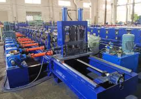
Used Purlin Roll Forming Machines for Sale Worldwide
Posted on Sunday, January 25, 2026
Pre-Owned Roll Forming Machines for Purlin & Structural Steel Profiles
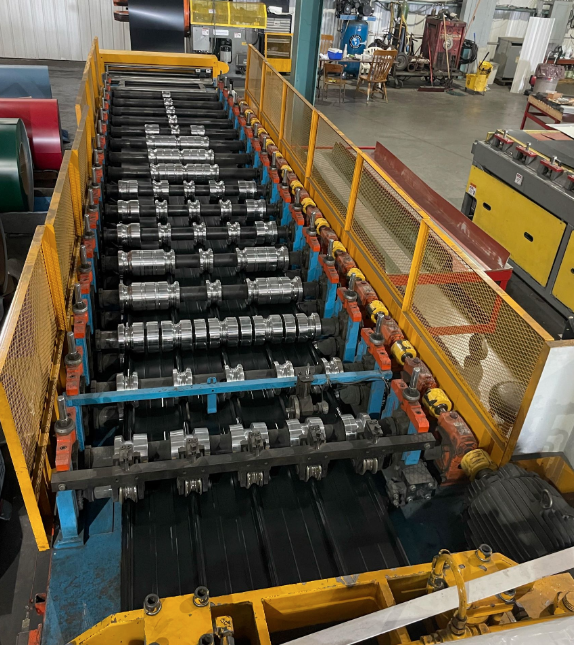
Used Roof Panel Roll Forming Machines for Sale Worldwide
Posted on Sunday, January 25, 2026
Pre-Owned Roll Forming Machines for Roofing Panel Production
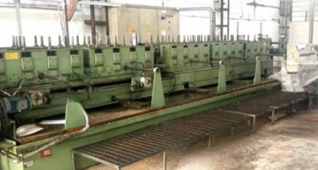
Used Roll Forming Machines for Sale Worldwide
Posted on Tuesday, January 20, 2026
Pre-Owned Roll Forming Machines with Inspection, Verification & Global Support
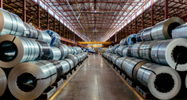
Steel Coil Supply for Roll Forming Machines Worldwide
Posted on Tuesday, January 20, 2026
Reliable Steel Coil Supply for Roll Forming, Fabrication & Manufacturing Applications
Copyright 2026 © Machine Matcher.