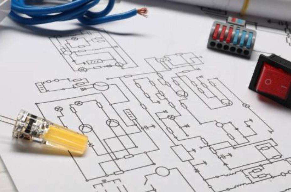
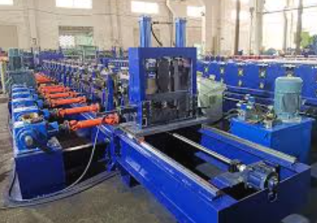
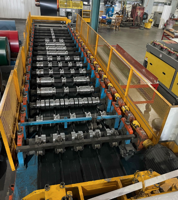
Creating a comprehensive electrical drawing for a roll forming machine is essential for ensuring efficient operation, safety, and easy maintenance.
1. Understanding the Components of a Roll Forming Machine
Before beginning the electrical drawing, it’s crucial to have a clear understanding of the components that require electrical connections. The typical components of a roll forming machine include:
- Main Motors: Powers the forming rolls, uncoilers, and runout tables.
- PLC (Programmable Logic Controller): Controls the machine's automation and operational sequence.
- HMI (Human-Machine Interface): Operator interface for controlling machine functions.
- Sensors: Proximity sensors, encoders, or pressure sensors for material positioning and safety checks.
- Drives and VFDs (Variable Frequency Drives): Controls motor speeds.
- Power Distribution Unit: Supplies power to all electrical components.
- Safety Circuits: Emergency stop buttons and interlocks for operator safety.
2. Electrical Standards and Symbols
Use standardized symbols and layouts to ensure that the drawing is clear and compliant with industry norms. Adhere to the following:
- Electrical Symbols: Use IEC or ANSI standards for the symbols of components such as motors, relays, switches, fuses, circuit breakers, etc.
- Labeling: All components, wires, and connections must be clearly labeled for easy identification.
- Compliance: Follow local electrical codes and standards such as:
- IEC 60204-1 for the electrical equipment of machines.
- NEC (National Electrical Code) for North America.
3. Power Distribution
Key Points:
- Power Source: Determine the machine’s electrical power requirements, including voltage (typically 220V, 380V, or 480V), frequency (50 Hz or 60 Hz), and phase (single-phase or three-phase).
- Main Circuit Breakers: Include a main circuit breaker to protect the entire machine from power surges.
- Power Distribution Panel: This panel distributes power to the various subsystems (motors, PLC, sensors, etc.).
- Transformers: If necessary, show the wiring of step-up or step-down transformers to adapt voltage to machine requirements.
Example:
plaintextCopy code<code>Main Power > Circuit Breaker > Power Distribution Panel > Components (Motors, PLC, Sensors)
</code>
4. Motor Control Circuits
Key Points:
- Wiring for Motors: Each motor needs a dedicated control circuit with start/stop buttons, relays, contactors, and motor protection devices (e.g., thermal overloads).
- VFD Integration: If VFDs are used for speed control, ensure that the wiring diagram shows how they are connected to the motors and controlled via the PLC.
- Emergency Stop: The emergency stop button must cut power to all motors immediately.
- Control Relays: Show how relays are used to control motor start and stop functions.
Example:
plaintextCopy code<code>Power Source > VFD > Motor > Thermal Overload > Contactors/Relays > Start/Stop Buttons
</code>
5. PLC and Automation System
Key Points:
- PLC Wiring: Show the connection between the PLC and all other components like motors, sensors, HMI, and safety circuits.
- Input/Output (I/O) Points: Clearly label each I/O point on the PLC, specifying whether it connects to a sensor (input) or motor/actuator (output).
- Communication Protocols: Indicate the communication system (e.g., Modbus, Ethernet/IP) used to integrate the PLC with other devices or control systems.
- Control Logic: Highlight how the PLC controls the machine's operational logic, including the sequencing of operations and safety checks.
Example:
plaintextCopy code<code>PLC Inputs: Sensor signals, Emergency Stop
PLC Outputs: Motor control, Alarms, HMI
</code>
6. Safety Circuit
Key Points:
- Emergency Stop Circuit: Ensure redundancy in the design, so the machine can be stopped at any point in time.
- Interlocks: Install interlocks on doors, hatches, or moving parts. If a door is opened, the machine should automatically shut down.
- Safety Relays: Show how safety relays are used to ensure the emergency stop and other safety features function correctly.
Example:
plaintextCopy code<code>Emergency Stop > Safety Relay > Motor/Power Disconnect
</code>
7. Sensor Integration
Key Points:
- Position Sensors: These sensors help detect the material position, ensuring proper alignment and feeding. Each sensor should have its wiring diagram, showing how it connects to the PLC.
- Safety Sensors: Use proximity sensors to detect potential obstructions or human presence in hazardous zones.
- Feedback Loop: Create a feedback system where sensors communicate with the PLC to ensure that the machine only operates when conditions are safe.
Example:
plaintextCopy code<code>Sensor > PLC Input > Processing Logic > Motor Output
</code>
8. HMI (Human-Machine Interface)
Key Points:
- Control Panel: The HMI is the control panel that allows the operator to start/stop the machine, adjust parameters, and monitor performance.
- Connection: Show the communication wiring between the HMI and PLC.
- Emergency Controls: The HMI should include emergency stop buttons and warning indicators.
Example:
plaintextCopy code<code>HMI > PLC > Motors, Sensors, Safety Circuits
</code>
9. Cable Management and Grounding
Key Points:
- Cable Routing: Ensure that cables are routed to avoid interference with mechanical operations and are protected from wear and tear. Use cable trays and conduits where necessary.
- Grounding: Proper grounding of all components is essential to avoid electrical shocks and system malfunctions.
- Noise Reduction: Use shielded cables for PLC and sensor wiring to prevent electrical noise from affecting the system.
Example:
plaintextCopy code<code>Grounding Terminal > Machine Frame > Power Supply, Motors, Sensors
</code>
10. Labeling and Documentation
Key Points:
- Component Labels: Each component (motors, relays, PLC, sensors) should have a unique identifier that matches the labeling in the electrical drawing.
- Wire Labels: Clearly mark each wire with its destination, voltage, and function.
- Electrical Drawing: The final drawing should include:
- A title block with the project name, date, and engineer’s signature.
- A revision history for updates.
- Detailed diagrams for all systems (power, control, safety, sensors).
11. Testing and Troubleshooting
Key Points:
- Initial Testing: Test all electrical systems before operation. Ensure all wiring is correct, motors are functioning properly, and safety circuits are operational.
- Common Issues: Document common electrical issues like short circuits, sensor misalignment, or PLC errors, and provide a troubleshooting guide.
- Monitoring: Install monitoring systems (e.g., voltmeters, ammeters) to allow easy identification of electrical problems during operation.
Example Troubleshooting Steps:
plaintextCopy code<code>Issue: Motor not starting
1. Check power supply and fuses.
2. Verify motor connections to VFD and PLC.
3. Test the emergency stop and safety interlocks.
</code>
12. Best Practices for Safety and Efficiency
- Redundancy in Safety Circuits: Always implement redundant safety features such as dual emergency stop buttons.
- Use of Shielded Cables: For control systems like the PLC and sensor wiring, shielded cables reduce interference and increase reliability.
- Regular Maintenance: Periodically inspect all electrical components, particularly high-wear parts like cables, sensors, and relays.
Conclusion
A well-designed electrical drawing for a roll forming machine is vital for ensuring safe, efficient, and reliable operation. By following the steps outlined in this guide, you can create a comprehensive schematic that integrates all electrical components, safety features, and control systems. Proper planning, compliance with electrical standards, and thorough testing will ensure long-term machine efficiency and operator safety.


